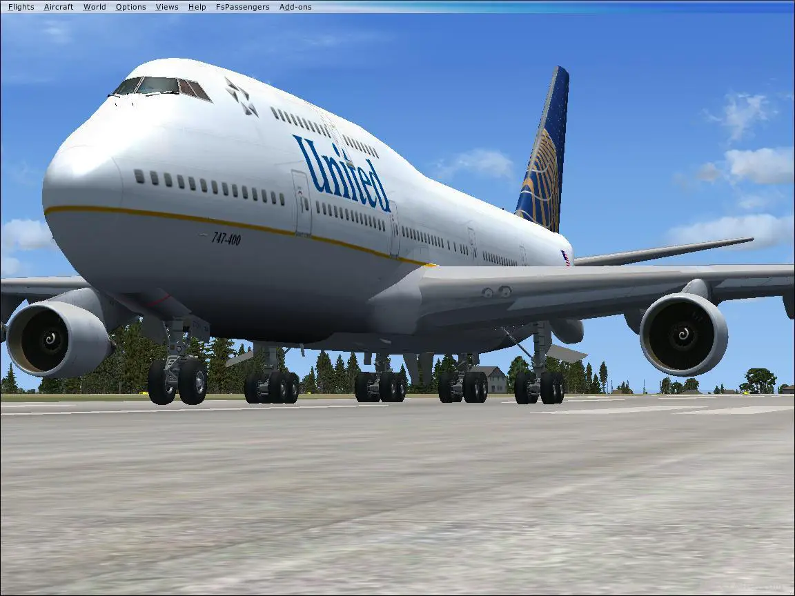

As was noted earlier there are several possibilities, from plain flaps to area extending flaps all with one, two or three slots. The drag due to the high-lift systems depends upon the types of trailing edge and leading edge flaps envisaged for the aircraft under consideration. Imperial units AD/q = 0.006 (Wi.)0 73 WL in lb and (AD/q) in sq ft metric units AD/q = 0.00093 (JFL)☇3 WL in kg and (AD/q) in sq mįor a quicker result just assume AD/q = 0.02 S (where S is the wing reference area). S ■ CDl.) where S is the wing reference area and WL is the weight/mass of the undercarriage.įor smaller aircraft in the F100, DC9 and B737 class, which will usually have twin-wheel main undercarriages, the following formula is suggested: Imperial units AD/q = 0.0025 (HQ073 WL in lb and (AD/q) in sq ft metric units AD/q = 0.00157 (WL)0 73 WL in kg and (AD/q) in sq m where AD/q is the increase in drag area (i.e. It is suggested that for aircraft with a multi-wheel bogie type undercarriage the following formulae may be used for undercarriage drag: The number of wheels and the general undercarriage size will be primarily influenced by the aircraft maximum landing weight. At the preliminary design stage much of this data will not be available. This is influenced by the size of the undercarriage and the number of wheels. For initial estimates you may use FQ = 1.25 for wing-mounted engines and a 20% higher value for aft fuselage-mounted installations (to account for the increased interference on the rear of the aircraft). Estimating the drag of a nacelle is complicated by the intricate geometry of many nacelles and the inter-relationship with the definition of engine thrust. Q = 1.0 for well filleted low/mid wings, = 1.1-1.4 for small or no fillet (a value of 1.0 to 1.2 seems to work for conventional designs) Where: A0 5c = sweepback angle at 50% chord

If = fuselage overall length Ax = fuselage cross-sectional area The form factors for each component are calculated from the input geometry using a specific formula for each component. Rec = Reynolds number of componentįor any component or area with laminar flow the following equation should be used:įor components with both laminar and turbulent flows the value for Cf should be a weighted (by area) average of the two results.

Where: M = Mach number at operational conditions under investigation.
DRAG AIRPLANE SKIN
The skin friction coefficient for turbulent boundary layer conditions can now be calculated for each component using the Prandtl-Schlichting formula:Ĭf = / fuselage overall length, wing mean chord, tail mean chord, nacelle overall length Re = (Vl)/u where: V = aircraft forward speed in the flight case under investigation u = kinematic viscosity at the speed and height of operation I = component characteristic length, i.e. We start by calculating the Reynolds number Re for each component: Where: Cf = skin friction coefficient which is a function of Reynolds number F = component form (shape) factor Q = interference factor Swet = component wetted area Sref = reference area used for the calculation of CD (normally the wing gross area) The profile drag can be estimated using the formula below: Each of the drag terms will now be assessed. The total drag coefficient can be plotted against Cl to give the graph shown inįig. As civil aircraft are not intended to be flown past the drag divergence Mach number this term may be assumed to be 0.0005 if no other details are available = total effect of all the lift dependent components (principally this is a function of CDj as the design becomes more established this term may be extended to include a direct CL term as well as the square term)ĪCDW = additional drag resulting from the shock waves. the summation of the drag from all the aircraft components appropriate to the flight conditions under investigation) CD. Where: CDo = estimated total profile drag coefficient (i.e.

These effects result in the following formations for aircraft drag coefficient: wave drag from shock waves as parts of the accelerated flow over the surfaces become supersonic. lift induced drag resulting from the changes in pressure due to attitude variations resulting from the generation of lift ģ. profile drag resulting from the pressure field around the shape and from the surface skin friction effects of the boundary layer Ģ. Each main component of the aircraft (wing, fuselage, tail surfaces, nacelles and in the low speed flight phases the flaps and undercarriage) must be separately assessed for its contribution to the overall drag of the aircraft.2 It is not sufficient to consider only the wing effects in the estimation of drag.įor subsonic civil aircraft the overall drag of the aircraft can be considered under three categories:ġ.


 0 kommentar(er)
